Coiled tubing damage is common in the industry, but many of the types of damage included in this Glossary can be avoided and/or repaired if identified early. This document aims to summarize the types of damage observed in the field and provide guidance on how to fix the tube as well as how to avoid causing damage from the beginning. Several terms are defined below which are used throughout the glossary.
Abrasive wear: the loss of material due to hard particles or hard protuberances that are forced against and move along a solid surface (ex: sanding with sandpaper or surface gouging)
Corrosion: Corrosion mechanisms can be present on the OD and ID surfaces, both macroscopically and microscopically. For instance, hydrogen embrittlement may only be observed at higher magnifications on the fracture face, whereas overall acid corrosion can dissolve the tube completely. All corrosion mechanisms can substantially reduce the predictability and fatigue life of the strings.
Erosive wear: caused by the impact of particles of solid or liquid against the surface of an object. The rate of erosive wear depends on the material characteristics of the particles: such as shape, hardness, impact velocity and impingement angle, as well as the material properties of the eroded material. For ductile materials like all grades of coiled tubing, the maximum wear rate occurs when the impingement angle is normal (90 degrees) to the surface.
Galling: a form of surface damage arising between sliding solids, distinguished by microscopic, usually localized, roughening and creation of protrusions above or below the original surface.
Damage Types Included In This Glossary:
TYPE 1: Plow Marks (Fish Scale or Chatter Marks)
TYPE 2: Injector Damage
TYPE 3: Injector Damage (Crescent Moons/Swoop Marks)
TYPE 4: Longitudinal Abrasion and Completion Damage
TYPE 5: Galling Damage
TYPE 6: Spooling Damage
TYPE 7: Washout and Erosion
TYPE 8: Waviness
TYPE 9: Corrosion – Internal
TYPE 10: Corrosion – Ponding/Storage
TYPE 11: Corrosion – Low pH (acidic) fluid exposure
TYPE 12: Corkscrew
TYPE 13: Collapse
TYPE 14: Stripper Failure/Mechanical Damage
TYPE 15: BHA Connector Failures
TYPE 16: Outside Diameter (OD) Chatter/ Scarfing Marks
TYPE 17: Hydrogen Embrittlement
APPENDIX A: Measuring Wall Thickness with UT Devices and Comparison with Physical Measurements
APPENDIX B: Measuring Tools for the Field
APPENDIX C: Field Damage Repair Guidelines
APPENDIX D: Failure Management and Sample Preparation for Extraction and Analysis
APPENDIX E: Pigging, Purging, and Storage Corrosion Mitigation
TYPE 1: Plow Marks (Fish Scale or Chatter Marks)
POSSIBLE SOURCE: Injector head gripper blocks, downhole debris, well completion components
DESCRIPTION: Plow marks are a severe form of galling causing localized surface deformation. This produces a localized change in mechanical properties including an increase in hardness and reduced ductility. The damage reduces the wall thickness locally and the material is “plowed” to a termination point commonly associated with a mass of material generally flush with the surface.
EFFECT ON FATIGUE LIFE: Plow marks are extremely detrimental to fatigue life. If not repaired immediately after the damage occurs, subsequent bending cycles will propagate cracks at the root of each of the impressions as shown below. This propagation occurs readily due to the reduction in ductility and elevated hardness also shown below. Limited tests have indicated residual fatigue life to be 10-50% of the base tube depending on tube geometry and operating parameters.
REPAIR: Repair of plow mark damage is recommended immediately. Measurements from limited samples have found depth of plow mark damage to range from 10-30% of base wall thickness. Remove the damage per Global Tubing’s “Managing and Repairing Field Defects” at the end of this document. Of specific importance with this damage is inspection using dye penetrant or magnetic particle testing after repair to assure all possible cracks are removed. Cycle tubing on and off the reel and re-inspect to assure all cracks are removed prior to use.
MITIGATION: Plow marks have several possible origins and each needs to be managed independently. INJECTOR HEAD – follow IH manufacturer guidelines for chain tension and skate pressure based on surface weight and snubbing forces. Tension and pressure will most likely need to be adjusted throughout the job to accommodate changing conditions. DOWNHOLE DEBRIS –maintaining good hole cleaning practices is essential. Monitor returns for expected cuttings at surface. Sufficient annular velocity and fluid rheology is necessary to carry all solids. Be sure to POH at a rate slower than the debris field (which is slower than the AV). To prevent buildup of debris in horizontal sections of the well, short trips back to vertical at scheduled intervals are suggested. WELL COMPLETION COMPONENTS – Thorough inspection of surface equipment and alignment prior to RIH.
EXAMPLE:

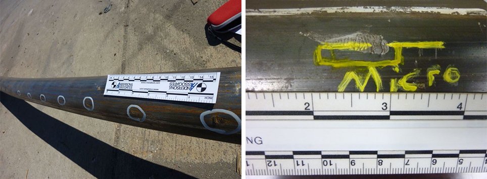

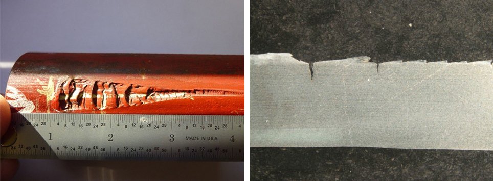
Plow Marks: Note the increase in hardness and fractures emanating from the root of the mechanical damage. Immediate repair is critical to reduce the amount of cracking at the root of this damage followed by nondestructive examination such as Magnetic Particle or Liquid Penetrant Inspection to assure complete removal of the cracking.
TYPE 2: Injector Damage
POSSIBLE SOURCE: High injector chain pressure, and loose chains during snubbing, injector shoe misalignment, ballooning of pipe can cause interference between injector shoes and pipe.
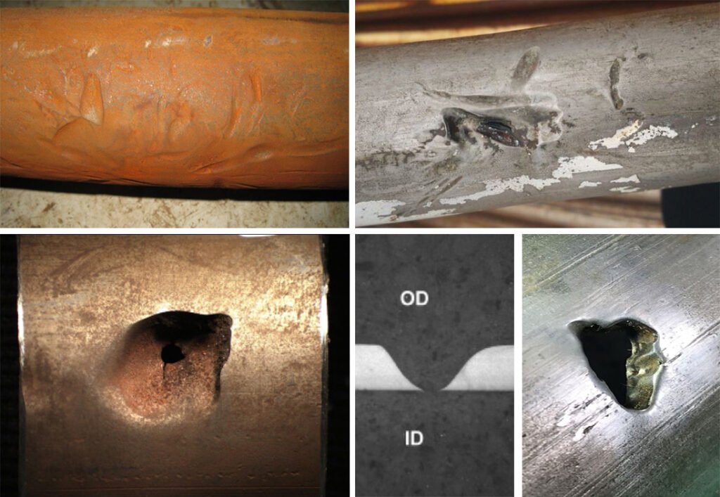
DESCRIPTION: Injector damage can be a combination of galling and abrasive wear. Normally, the orientation of this damage is in the transverse direction. The depth of the damage can be inconsistent depending on the tubing mechanical properties and injector parameters. Generally, damage of this type is shallow (<10% of base wall thickness) but can cause subsequent failure due to fatigue and subsequent wall reduction.
EFFECT ON FATIGUE LIFE: Transverse marks are detrimental to low cycle fatigue life. Normally, the shallow depth of such damage limits the reduction in fatigue life.
REPAIR: Repair of transverse injector damage is recommended when possible. Remove the damage per Global Tubing’s “Managing and Repairing Field Defects” at the end of this document. However, many of these exceed 10% in depth or thin down with subsequent fatigue causing early failure.
MITIGATION: Follow injector head manufacturer’s guidelines for chain tension based on snubbing forces seen during operations. As conditions change during operations, adjust chain tension accordingly.


POSSIBLE SOURCE: Suspected source of damage is surface equipment.
DESCRIPTION: Periodic OD indentations cause the ID to become smaller (red arrows) which causes a hinge effect and subsequent bending causes the wall thickness to neck down (yellow arrows).
EFFECT ON FATIGUE LIFE: Not repairable. Reduction in wall thickness and localized changes in hardness causes a reduction in tensile capacity.
MITIGATION: Frequent inspection of surface equipment and monitoring skate pressure and chain tension as well as alignment of gooseneck entry into the injector.


TYPE 3: Injector Damage (Crescent Moons/Swoop Marks)
POSSIBLE SOURCE: Misaligned gooseneck, incorrect mounting of gripper block, wrong size of gripper block.
DESCRIPTION: Crescent moons are a form of abrasive/galling wear and are relatively smooth and uniform. This damage is imposed by the corner edge of coiled tubing injector head gripper blocks.
EFFECT ON FATIGUE LIFE: The orientation of this damage and the method of imposition result in minor reduction in low cycle fatigue life. Normally, the depth of this damage is less than 10% of the base wall thickness. More severe instances of this damage (10% or more of base wall thickness) may decrease fatigue life.
REPAIR: Repairing this damage type is recommended for the most severe cases. Remove the damage per Global Tubing’s “Managing and Repairing Field Defects” at the end of this document.
MITIGATION: GOOSENECK ALIGNMENT – Ensure gooseneck is properly aligned in relation to the coiled tubing unit, as well as the injector head itself. GRIPPER BLOCKS – Monitor gripper block condition and securement to the chains on a regular basis. Follow injector head equipment manufacturer guidelines for chain lubrication and gripper block securement.
EXAMPLE:


TYPE 4: Longitudinal Abrasion and Completion Damage
POSSIBLE SOURCE: Running into completion with high deviation, running into a completion with no fluid or other friction reducing agent, running into dry chrome completions, local bends in pipe near BHA.
DESCRIPTION: Abrasion damage can be a combination of galling and abrasive wear. Normally, the orientation of this damage is in the longitudinal direction.
EFFECT ON FATIGUE LIFE: Because the orientation of most completion damage is in the longitudinal direction due to sliding wear of the pipe against the casing, the detrimental effect on fatigue life due to the damage itself is minimal if the wall loss is minimal. The primary failure mode is burst or collapse as shown in the images below.
REPAIR: Repairing longitudinal abrasion damage and scratches will have a minimal improvement in fatigue life. If wall thicknesses are within specification, it is better to not repair. If wall thicknesses are measured to be below specification, then it is recommended the section be removed completely.
MITIGATION: Constant pipe movement is essential especially when in the horizontal section of the well. Watch for abrasion, especially near the coil connector. Trim pipe on a regular basis regardless of any indication of abrasion. Use of friction reducers can also reduce the propensity to this type of damage. Watch for spooling damage such as shown in the “Wave” section of this report which can cause localized abrasion. Attempt to crop strings near the BHA in the straightest area to attach BHA’s. See subsequent section on BHA connector failures. This minimizes localized contact normal forces and reduces propensity to abrasion. Short trips may reset the helix when spending a lot of time on one plug and focus the abrasion in a different location.
EXAMPLE:

TYPE 5: Galling Damage
POSSIBLE SOURCE: Abrasion from contact with casing and/or coupling.
DESCRIPTION: Galling is a form of abrasion where adhesion of the two contact surfaces removes material from one contact surface while adhering it onto the adjacent contact surface, or “moves” the surface material relative to the substrate.
EFFECT ON FATIGUE LIFE: Damage in the axial direction may have minimal impact on fatigue, however excessive wall loss will reduce pressure capacity and fatigue.
REPAIR: Not repairable.
MITIGATION: Use of friction reducers and monitoring highly deviated well profiles for areas most susceptive to high normal forces.
EXAMPLE:

TYPE 6: Spooling Damage
POSSIBLE SOURCE: Tight wrapping during spooling especially while making the change from one layer to the next, spooling while the tubing is dry, yard spooling with large angle from one spool to the other, loose spooling of the tubing, misalignment of gooseneck while reeling.
DESCRIPTION: Spooling damage is normally transverse galling. The orientation of this damage on the tubing is generally either the outer surface of the tube, or 90 degrees from the outermost surface of the tubing while on the spool. The depth of spooling damage ranges from 0-20% of base wall thickness. High grade (90+ksi yield strength) and large OD (2” +) have a greater propensity for spooling damage due to increased contact forces involved during spooling.
EFFECT ON FATIGUE LIFE: The orientation of this damage on the tube effects fatigue life. Because the damage is transverse, the reduction in low cycle fatigue life is moderate. Quantifying the reduction in fatigue life is difficult due to the varying depth and length of damage.
REPAIR: Repairing spooling damage is recommended. Remove the damage per Global Tubing’s “Managing and Repairing Field Defects” at the end of this document. Check for cracking after repair by MPI or LPI after spooling to assure the entire crack is removed.
MITIGATION: Use good spooling practices. Wraps should be tight, and even throughout the reel. Avoid crossing over previous wraps and any gaps in the corners of the reel. Lubricate pipe on reel while spooling.
EXAMPLE:

TYPE 7: Washout and Erosion
POSSIBLE SOURCE: Static coiled tubing downhole in close proximity to perforations, flow tees, broken casing collars, or other jetting sources with sand (or other abrasive) and fluid. Localized flow cuts are often observed after keeping the pipe stationary for too long.
DESCRIPTION: Washout damage is a type of erosive wear. Washouts are typically very smooth and non-uniform in shape and depth. They are also independent of tube grade and hardness.
EFFECT ON FATIGUE LIFE: Washout damage reduces fatigue life by reducing the tubing wall thickness. The smooth nature of washout damage is less detrimental than damage of the same depth with jagged, point contacts, but because the shape and depth of washouts are impossible to predict, the reduction of fatigue life is also difficult to predict. Most likely, the reduction in fatigue life is large due to the aggressive nature of erosion.
REPAIR: Normally, this sort of damage is considered irreparable. If chosen to remove the damage, use Global Tubing’s “Managing and Repairing Field Defects” at the end of this document, or remove completely and perform a tube-to-tube butt weld.
MITIGATION: Keep pipe moving at all times during the operation, especially when cleaning/returning a high volume of abrasive debris or taking returns at a high velocity. Using a flow cross instead of a flow tee at the well head which allows for multiple fluid flow paths and reduces the chances of flow path impingement.
EXAMPLE:
TYPE 8: Waviness
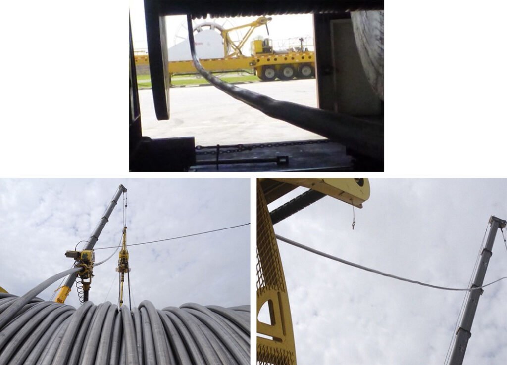
POSSIBLE SOURCE: Loose or uneven wrap during spooling, gaps or overlapping wraps, flange interference causing overlapping and localized waviness.
DESCRIPTION: Waviness in the tubing is a type of deformation that is apparent by gradual undulation in the tubing. Waviness is a product of either poor wrapping quality (abrupt changes in the tubing wraps or gaps) or at crossovers (the change in spooling direction at the flanges).
EFFECT ON FATIGUE LIFE: Wave deformation is not considered detrimental to long term performance of the tube and generally goes away after a few trips. Abrupt changes can however cause localized abrasion if the localized areas remain after several trips.
REPAIR: Subsequent plastic deformation (normal spooling) will reduce the appearance of this type of anomaly. Inducing a reverse bend will expedite removal of the wavy appearance.
MITIGATION: Use good spooling practices; wraps should be tight and even throughout the reel. Avoid crossing over previous wraps and any gaps in the corners of the reel. Coiling similar to lower left photo should be avoided. Lubricate pipe on reel while spooling.
TYPE 9: Corrosion – Internal
POSSIBLE SOURCE: Inadequate corrosion inhibition during job or improper storage after job with residual fluids inside, no purging procedure, uncapped ends during storage, and uninhibited fluids left from previous jobs.
DESCRIPTION: Internal corrosion from residual fluids or corrosive environment inside the string.
EFFECT ON FATIGUE LIFE: Corrosion can substantially reduce fatigue life because cracks propagate from the roots of the corrosion pits.
REPAIR: Normally, repair is not possible. Prevention and maintenance are the key to minimizing corrosion damage.
MITIGATION: Use a combination of wiper balls, wire brush pigs, biocides, inhibitors, and high-quality nitrogen to store strings between jobs. Proper chemical treatment will depend on the types of jobs performed, the fluids pumped, and the time between jobs.
Note: Circulation of Nitrogen only – without a wiper or pig – generally leaves 2-3bbls of fluids inside the reel.
EXAMPLE:

TYPE 10: Ponding and Storage Corrosion
POSSIBLE SOURCE: Improper pigging and/or lack of adequate corrosion inhibition program allows for biofilm buildup.
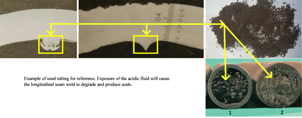
DESCRIPTION: In between jobs, 2-3bbl of fluids are typically left in CT strings even after N2 purge, especially when pigs/wiper balls are not used during the purge. This fluid allows for the development and build-up of a biofilm that creates scale and corrosion pits.
EFFECT ON FATIGUE LIFE: Not repairable.
MITIGATION: Frequent pigging of the coil will reduce scale buildup and limit ponding corrosion by breaking up biofilm and allowing chemical treatments to penetrate to the surface of the tubing rather than the rust film.
EXAMPLE:


TYPE 11: Corrosion – Acidic fluid exposure
POSSIBLE SOURCE: The result of extended and unmitigated exposure to low pH (acidic) fluid. Improper and/or lack of adequate acid inhibition program allows for dissolution of CT material.
DESCRIPTION: Corrosion pitting comprised of multiple hemispherical overlapping pits. The pitting may severely reduce the wall thickness on either OD or ID surface depending on the exposed surface.
EFFECT ON FATIGUE LIFE: Not repairable.
MITIGATION: Proper chemical treatment and fluid management ensuring adequate neutralization and use of soda ash between jobs to assure ID weld bead remains intact, and OD surface does not suffer further corrosion attack.
EXAMPLE:


TYPE 12: Corkscrew
POSSIBLE SOURCE: Over torque or sudden increase in compressive force that exceeds the limits of the tubing.
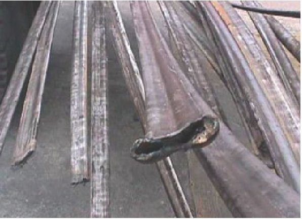
DESCRIPTION: Corkscrew is a type of deformation where the tubing is plastically deformed in a twisted shape
EFFECT ON FATIGUE LIFE: Corkscrew deformation is considered detrimental to the affected sections and continued use will lead to abrasive damage against the well tubing/casing which can substantially reduce the wall thickness.
REPAIR: Normally, this sort of damage is considered irreparable. Recommended action is to remove the corkscrewed sections.
MTIGATION: Correct motor selection based on max torque output and CT torque capacity is essential. When moving after a motor stall, reduce pump rate temporarily to reduce pressure and decrease any counter rotation. Monitor weight while RIH, especially during operations with large casing size compared to CT OD.
EXAMPLE:

TYPE 13: Collapse
POSSIBLE SOURCE: Over pressure in annulus, or reduction in wall thickness can initiate collapse.
DESCRIPTION: The pressure differential between the annulus and tubing exceeds the allowable capacity of the tube. This causes the tube to collapse.
EFFECT ON FATIGUE LIFE: Significant
REPAIR: This sort of damage is considered irreparable. Recommended action is to remove the collapsed sections.
MITIGATION: Constantly monitor pressure and ensure conditions stay within acceptable von Mises stress limits. Consider that the worst-case condition may not be on surface, but downhole.
EXAMPLE:

TYPE 14: Stripper Failure/Mechanical Damage
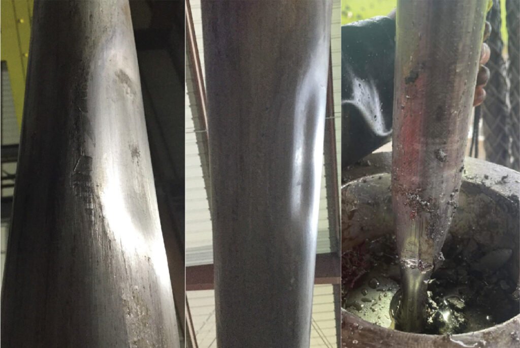
POSSIBLE SOURCE: Stripper packer failure lodged in between tube and stripper causing compressive damage to the tube surface. Debris build up inside the stripper pushes onto the CT OD, causing collapse.
DESCRIPTION: Stripper packer failure caused packer parts to lodge in between tube and stripper, leading to compressive damage on the tube surface. Debris can also build up at surface against the stripper while pulling out of hole and cause collapse.
EFFECT ON FATIGUE LIFE: The smooth transition may have a small impact on fatigue for small impressions, but the depth of the damage should be considered for detrimental reduction in collapse capacity and should only be used a few times with constant monitoring if necessary.
REPAIR: Normally, this sort of damage is considered irreparable. Measure depth of compression to determine extent of damage and run collapse calculations for future operations.
MITIGATION: Ensure regular maintenance of the stripper and the lubricator is performed to prevent failure.
TYPE 15: BHA Connector Failures
POSSIBLE SOURCE: BHA connector failures can come from several sources including welding technique, groove rolling technique, dimpling technique, tube cropping technique, localized abrasion etc.
DESCRIPTION: Partial failure or complete separation of the BHA from the UH portion of the tube.
MITIGATION: the following areas are addressed individually, Weld Failure, Groove/Dimple Failure, pin end connection failure, and abrasion failure
EXAMPLE:
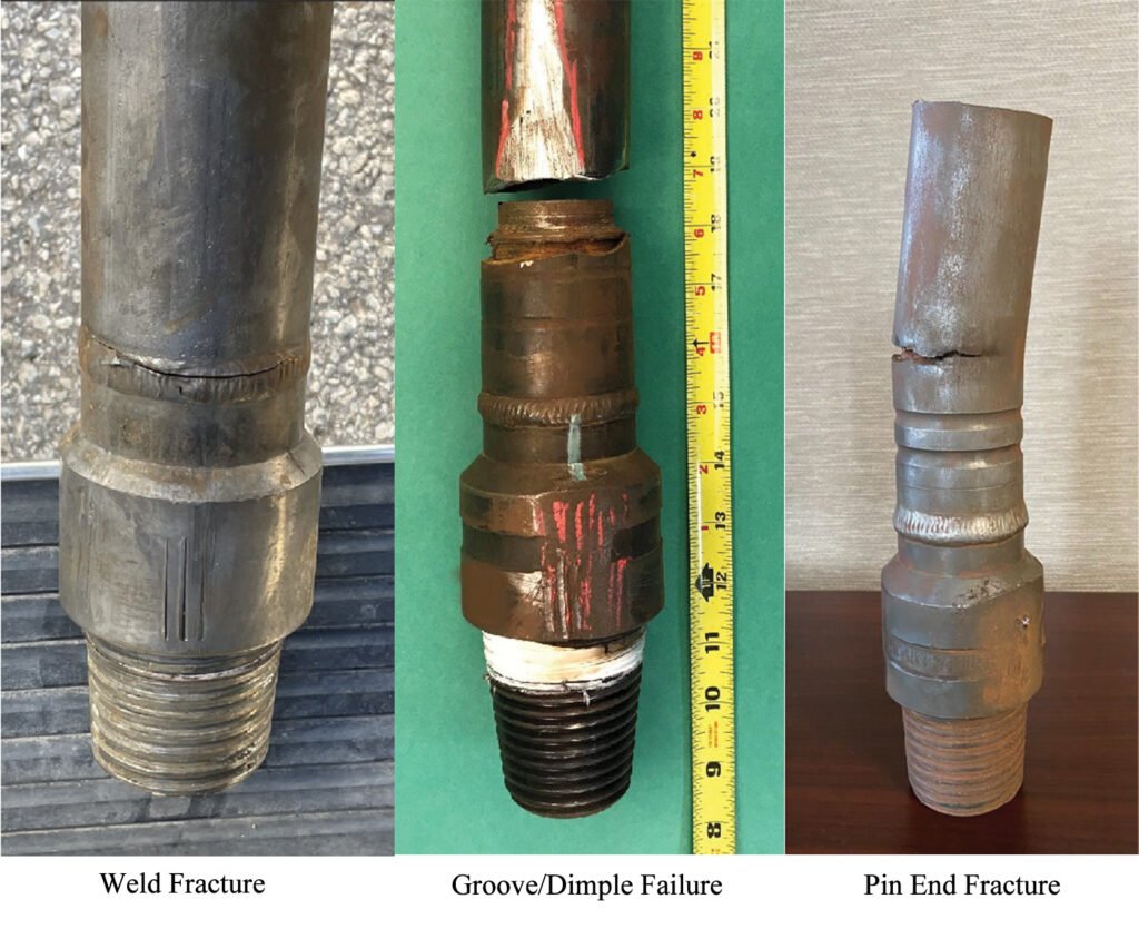
WELD FAILURE MITIGATION: Stress at the root of the welds depends on the amount of space between the pin end and the coil. Any space should be taken up on the pin end of the connector by a small weld bead to reduce the localized stress. A rolled groove or pins also stabilizes the pin end and minimizes the bending stress on the weld. Leave enough gap between the pin side and tube side to allow for adequate penetration into the connector base. Only use 4130 or 1018 type low carbon materials for the pin connections and GT recommends ER80S-D2 or 90S-B3 weld consumables. Anything stronger tends to have less ductility and overmatches compared to the pin connector strength levels. No chill blocks and slow cooling after welding (no quenching).
EXAMPLE:

GROOVE AND DIMPLE FAILURE MITIGATION: The most common type of failure is when the depths of the grooves are not centered on the pin itself. See below where the centerline of the groove is extruded toward the UH direction. It is critical the centerline of the grooves be marked after each of the previous grooves, DH to UH and successively shallower or per BHA manufacturer’s instructions. The third groove below was centered on the edge of the BHA connector groove and caused failure. Also, the depth of these grooves is not adequate and needs to be checked in the field using a pit micrometer to assure adequate depth accomplished.

PIN END FRACTURE/ABRASION FAILURE MITIGATION: Failures immediately at the pin end of the BHA connector, or within proximity as shown below, are commonly caused by bent or kinked tubing not being cropped during BHA connector installation. A localized bend that causes additional stress at the connector can cause a premature bending failure as shown below. Cropping at a point where the tangent of the curve is perpendicular to the wellhead is critical.

A localized kink or bend adjacent to the connector can cause high normal forces on the casing cause premature failure due to abrasion where the high normal forces caused by the kink selectively wear against the casing and cause a low wall thickness causing subsequent failure.


TYPE 16: Outside Diameter (OD) Chatter/ Scarfing Marks
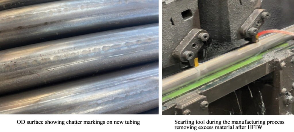
POSSIBLE SOURCE: Scarfing process during the high frequency induction (HFI) welding of the longitudinal seam weld.
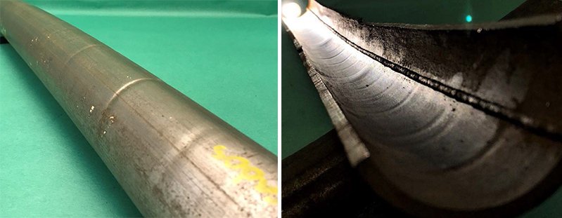
DESCRIPTION: The wavy appearance on one plane of the tube is aligned with the longitudinal weld seam. During high frequency induction longitudinal seam welding, the outside weld bead is mechanically removed with a carbide tool. The scarf removal is part of the manufacturing process of all coiled tubing strings to create perfectly round tubing. The chatter is a result of small vertical movement during the removal process.
EFFECT ON FATIGUE LIFE: OD chatter is superficial, and is not detrimental to the mechanical properties and integrity of the tubing and is does not cause issues during operations.
REPAIR and MITIGATION: No repairs or mitigation are necessary.
EXAMPLE:
TYPE 17: Hydrogen Embrittlement
POSSIBLE SOURCE: H2S exposure or Acid Stimulation with inadequate inhibition programs, or delayed operations.
DESCRIPTION: Intergranular hydrogen embrittlement causes sudden and often catastrophic failure when high strength tubulars are exposed to free hydrogen including acid and H2S. Presence of H2S increases the hydrogen permeability because it acts as a recombination poison for Hydrogen gas and allows more free hydrogen to enter the steel matrix and cause damage. Coiled tubing is manufactured from carbon steel which is similar compositions to other high strength materials such as 4130 and P110. Institutional knowledge demonstrates these high strength materials do not perform well when exposed to free hydrogen and inhibition practices should be well maintained when considering the use of high strength coiled tubing in these environments.
EFFECT ON FATIGUE LIFE: Embrittlement failures are often isolated but immediate and can occur on the reel, or downhole when exposed to untreated acid or H2S. See SPE paper 218327 for more information.
REPAIR and MITIGATION: No repairs are possible. Mitigation of Hydrogen damage is by careful adherence to inhibition procedures, pumping pills of inhibitor prior to use and during operations. Simple mass loss tests to screen for tubing compatibility may not be enough. Pitting and metallographic examination may be necessary to assure acid compatibility. Temperatures, and exposure times should be considered when testing for compatibility.
EXAMPLES: OD and ID cracking on the left, longitudinal weld seam in the center, and mid wall on the right, all have some characteristics of intergranular embrittlement shown at the bottom.
EXAMPLE:


